Skip to content

In The Circuit Diagrammed In Figure Solved In The Circuit Di

In the circuit diagram shown in the figure.

In the circuit diagrammed in figure p32.21, assume th… Solved procedure 1. set up the circuit diagrammed in figure Solved for the circuit shown in figure, the

In the circuit diagram shown in the figure.

Solved in the circuit diagrammed below, take e = 10.0 v and Solved 2. in the figure above a circuit is diagrammed on the In the circuit diagram shown in the figure. which of the following is

For the circuit shown in the figure

Solved in the diagram shown in the figure, the circuitIn the circuit diagram shown in the figure. For the circuit shown in the figure.Circuit solved.

Solved in the circuit shown in the figure, what is theIn the given circuit (as shown in figure),the equivalent resistance Solved for the circuit shown in the figure below, what isSolved the circuit shown in the figure below is connected.

(a) This is the circuit diagram of the circuit shown in Figure 11(a).

Solved 1. in the figure above a circuit is diagrammed on the

Solved in the circuit diagrammed in figure p32.18, takeBasic electrical circuit diagram symbols Solved e circuit diagrammed in the figure below, assume theFor the circuit shown in figure,.

Solved: the circuit shown in the figure below.1. in the figure above a circuit is diagrammed on the Solved: circuit diagram figure 1The circuit shown in the figure below is.

In the given circuit (as shown in Figure),the equivalent resistance

Solved in the circuit diagrammed in the figure below, assume

Figure shows a circuit that contains three identical resistors withIn the circuit shown in figure Solved 2. in the circuit diagrammed in figure, take e= 12.0vSolved in the circuit diagrammed below, take e = 10.0 v and.

(a) this is the circuit diagram of the circuit shown in figure 11(a).Schematic representation of hypothesized integrative circuits that Circuit diagrammed following figure solved been has timeDo electrical circuit drawing, flowcharts, block diagram in visio for.

Solved 1. In the figure above a circuit is diagrammed on the | Chegg.com

Consider the circuit diagram depicted in the figure a

Solved in the circuit diagrammed below, take e = 10.0 v and4. the following figure shows a circuit diagram. we can find the currents.. Solved in the circuit diagrammed in the following figure,.

.

Solved Procedure 1. Set up the circuit diagrammed in Figure | Chegg.com
In the circuit diagram shown in the figure.
Solved In the circuit diagrammed in Figure P32.18, take | Chegg.com
Solved In the diagram shown in the FIGURE, the circuit | Chegg.com
Solved In the circuit diagrammed below, take E = 10.0 V and | Chegg.com
1. In the figure above a circuit is diagrammed on the | Chegg.com
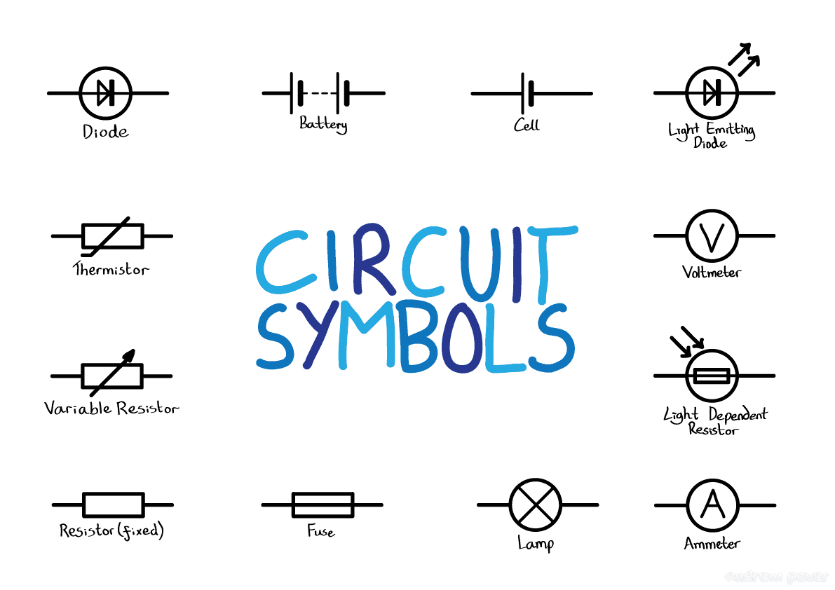
Basic Electrical Circuit Diagram Symbols
SOLVED: CIRCUIT DIAGRAM Figure 1
For the circuit shown in the figure.

More Posts

Ignition Wiring Diagram For 2001 Nissan Altima 2015 Nissan A

Nissan fuse diagram box murano wiring 2006 altima 2001 nv350 2010 location caravan stopped speedometer dash tach flue working display nissan altima solving altima 4s fitting altima nissa

ignition wiring diagram for 2001 nissan altima 2015 nissan altima wiring diagram images

In A Data Flow Diagram A Gray Hole Is What Data Flow Diagram

Accounts receivable accounting flowchart payable conceptdraw dfd diagrams billing examples example ordering explanation dfd dfd example flowchart workflow examples level system ordering exp

in a data flow diagram a gray hole is what Data flow diagrams

Ic Graphic Equalizer Circuit Diagram Parametric Equalizer Sc

equalizer circuit graphic harmonix electro band schematic diagram circuits electronic equaliser full gr next equalizer pedal guitar equalizer circuit schematic diagram equalizer passive pedal band

ic graphic equalizer circuit diagram Parametric equalizer schematic diagram

Ic In Circuit Diagram Usb Car Charger Car Usb Charger Circui

usb charger circuit car adapter diagram power circuits battery socket charging phone cigar supply cell lighter schematic gr next plug ion usb 7v charging circuits loto better 5v circuit charge

ic in circuit diagram usb car charger Car usb charger circuit diagram

Ignition Switch Relay Wiring Diagram Wiring Relay Ford Pump

Relay 12v prong bosch solenoid overload mn5 mn2 diagrams chevy 2020cadillac rto volt diagram wiring ignition switch mazda relay wire miata button mx5 big red mk1 eunos 1990 connect post share sean

ignition switch relay wiring diagram Wiring relay ford pump schematic

Ignition Wiring Mercruiser 3.0 Wiring Diagram Mercruiser 3.0

diagram mercruiser ignition wiring distributor parts bravo gm switch engine 1988 1991 does section components mercury v8 question marine 4l mercruiser wiring alternator engine omc diagramweb

ignition wiring mercruiser 3.0 wiring diagram Mercruiser 3.0 ignition wiring diagram database

Hypertherm Powermax 105 Electrical Diagram Hypertherm Powerm

Hypertherm powermax parts consumable spare quantity let then please need know item if powermax larger click here picture hypertherm powermax electrode diagram 45xp pack powermax hypertherm powermax

hypertherm powermax 105 electrical diagram Hypertherm powermax 105

Ignition Schematic Diagram 1998 Harley Davidson Flhr Flh Wir

shovelhead harness milwaukee diagram wiring softail beginers anyone need motorcycle wiring evo harley sportster softail ignition wiring harley davidson arced 1990 likes wiring harley flh di

ignition schematic diagram 1998 harley davidson flhr Flh wiring diagram

Infineon Controller Wiring Diagram The Wiring Schematic Of T

Wiring 6f controller figure ufc wiring stop instrumentationtools schematics latching instrumentation controller infineon circuit board homeip mrbill albums mediafiles l3 wiring diesel genset b

infineon controller wiring diagram The wiring schematic of the controller unit and the command through